Workflow
Process Flow
This variant (main menu ☰ → Process Flow) allows for a virtually automated workflow. It merely requires the initial pick of the intended scans (sidebar on the right) and subsequent selection of the individual processing steps the user wishes to apply to the chosen data (fig. 5).
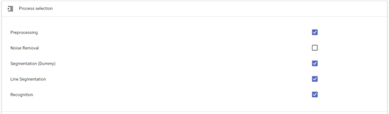 fig. 6. 'Process flow' Subcomponents.
In order to complete the process, choose an appropriate OCR model (or model package, composed of five individual models working simultaneously and in concert – see chapter 4.7). Simply go to ‘setting’ → ‘recognition’ → ‘general’ (as illustrated in fig. 6) and choose from the list of available OCR models (‘line recognition models’ – ‘available’).
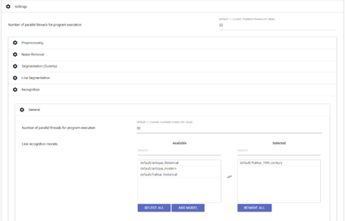 fig. 7. Selection of an appropriate OCR model.
Although it is generally possible to choose more than one recognition model, this is only recommended if the scans in question contain more than one printing type.
Finally, start the ‘process flow’ by clicking on ‘execute’. The current stage of this automated processing is translated into the progress bars and can be reviewed at any time. After the workflow’s completion, the results can be verified under the menu item ‘ground truth production’ (☰) .
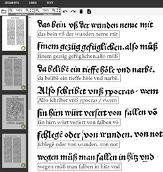 fig. 8. Individual lines with their corresponding OCR results.
If the OCR’s line-based results immediately meet the desired or required accuracy of recognition, final results can be generated (TXT and / or PAGE XML) under menu item ‘result generation’. Were those results not to meet the user’s requirements, they can be once more corrected before the final generation (see chapter 4.8).
Aside this ‘process flow’, OCR4all additionally provides the option of a sequential workflow which enables the user to independently execute the software’s individual submodules (see fig. 1) and their components, thus ensuring the proper correctness and quality of the generated data. Considering that these submodules are built on one another, the sequential workflow seems to be the most adequate choice when working with early modern prints and their intricate, complex layout.
We recommend first-time users execute the sequential workflow at least once (as described below) in order to understand the submodules’ operating principles.
Preprocessing
Input: original image (in colour, greyscale or binarized)
Output: straightened binarized or greyscale image
- This processing step is meant to produce binarized and normalized greyscale images, a basic requirement for a successful segmentation and recognition.
- Proceed by selecting the relevant scans (sidebar on the right) – the settings must remain unchanged (‘settings (general)’ and ‘settings (advanced)’), meaning that the images’ angle as well as the automatically generated number of CPUs used by this particular submodule don’t vary either (the latter pertains to all of OCR4all’s subsequent submodules).
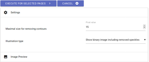 fig. 9. Pre-processing settings.
- Click on ‘execute’ to start binarization. The progression of this work stage can be tracked on the console, more accurately the ‘console output’. Warnings might be issued during the binarization process (in ‘console error’) which have no incidence on the binarization results.
- In order to check the binarization’s success, simply go to ‘project overview’ and click on any page identifier then on the display option ‘binary’. In addition, all processed pages should be marked with a green check mark in the project overview.
Noise Removal
Input: polluted binarized images
Output: binarized images without (or with very little) pollution
-The noise removal option helps to get rid of small impurities such as stains or blotches on the scans
- Proceed by clicking on ‘noise removal’ (main menu) and selecting the scans you wish to process on the right side of your display. You should initially conserve the default settings and, after clicking on ‘execute’, check the initial quality of the results: simply click on the designation of the scan you wish to verify (right sidebar); the ‘image preview’ option will provide you with a side by side comparison of the image before and after the noise removal. Please note that red elements will be deleted by this step.
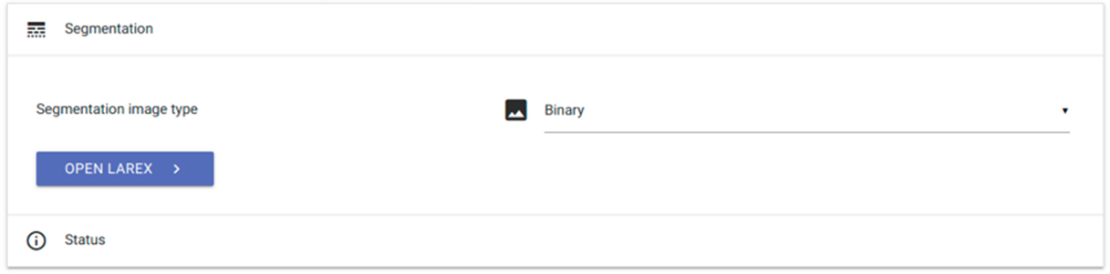 fig. 10. Noise removal settings.
- If too many interfering elements remain on the image, slightly adjust the ‘maximal size for removing contours’ factor upwards and repeat the step by clicking once again on ‘execute’ and subsequently reviewing the results.
- If too many elements were removed from the image, readjust the ‘maximal size…’ factor downwards.
- Try again until the results are satisfactory.
Segmentation – LAREX
Input: pre-processed images
Output: structural information about the layout regions (type and position) as well as reading order
LAREX is a segmentation tool which structures and classifies a printed page’s layout with regard to its later processing. LAREX is based on the basic assumption that the pages of early modern prints are composed of a recurring array of layout elements whose composition, although always book-specific, is largely consistent. Thus, the user is provided with different tools and resources whose aim it is to adequately structure and segment a printed page in order to catalogue all layout-related information necessary to the workflow’s subsequent steps. Besides the basic distinction between text and non-text (e.g. text vs. image/woodcut) and its further specifications (e.g. text headline, main text, page number etc.), this also includes information about the page’s reading order, i.e. the reading and usage order of the available layout elements.
Initial Settings
- Menu: click on ‘segmentation’, then on ‘LAREX’
- Go to ‘Segmentation image type’: select ‘binary’ if you will be working with binarized images, or ‘despeckled’ if the images went through the noise removal process
- Click on ‘open LAREX’ → LAREX will open in a new tab
 fig. 11: LAREX settings.
Once LAREX has opened, the first one of the pre-selected pages will be visible at the centre of your display, including a few initial segmentation results, which are generated by the automatic segmentation each page undergoes when initially opened with LAREX. Please note that these results are not saved. From there, the user will have to adjust the settings, tailoring the initial segmentation results to their particular work’s layout and undertaking a manual post-correction to ensure segmentation accuracy.
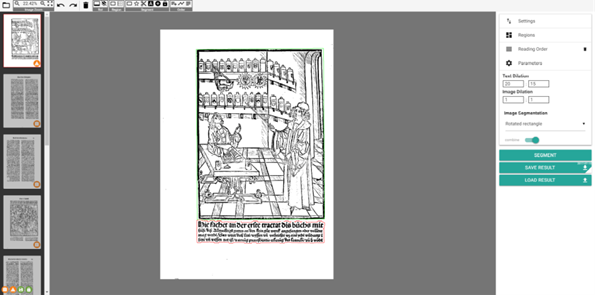 fig. 12. LAREX interface with automatic segmentation results.
Overview and toolbar
The left sidebar displays all previously selected scans. Colour-coded markings visible in the bottom right corner indicate the current stage of each scan’s processing:
- Orange exclamation mark: “there is no segmentation for this page” – no current segmentation results for this page
- Orange warning sign: “current segmentation may be unsaved”
- Green floppy disk: “segmentation was saved for this session” – segmentation results have been saved as an XML file
- Green padlock: “there is a segmentation for this page on the server” – individual previously saved segmentation results (c.) have been marked as correct after completion of the entire document’s segmentation (see below).
fig. 13. Different display modes.
- With the buttons '0' and '1' it is possible to switch between the binarized (black and white) and the normalized (grayscale) display mode. This selection is noted for all remaining pages of the project. It is possible to change the display mode again at any time.
- In the topbar, you will find different tools and tool categories pertaining to navigation and image processing:
 fig. 14. Different menu items in the toolbar.
- Open a different book: No settings adjustments necessary for all LAREX versions as integrated in OCR4all.
- Image Zoom: Enables general settings for image or scan display, such as zoom options. However, these can also be adjusted with your mouse and/or touchpad: shift the displayed page by left click-and-holding and moving your mouse; zoom using mouse wheel or touchpad.
- Undo und Redo: Undo or redo last user action. Even common key combinations are possible (i.g. CTRL + Z for undo last action).
- Delete selected items: Delete currently selected region.
- RoI, Region, Segment, Order: In addition to the right sidebar, these are the different options for processing and segmenting scans. While the options featured in the toolbar generally pertain to the current scan’s processing (see below), the right sidebar features project-wide options across all scans.
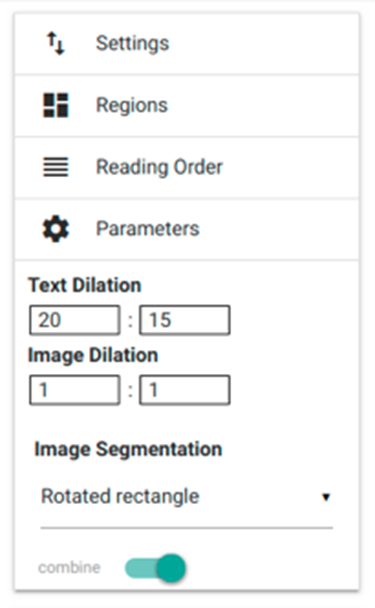 fig. 15. Right sidebar’s settings.
However, the latter can be amended, changed or adjusted at any time. In this case, we recommend saving all previously carried-out settings, whether they be related to recognition parameters (‘parameters’) or to document-specific layout elements (‘regions’) previously determined by the user, in ‘settings’. This will ensure these particular settings are applied the next time you work with this tool, enabling you to work with document-specific settings from then on.
Specific settings: ‘regions’, ‘parameters’, ‘reading order’, ‘settings’
- 'Regions': In accordance with the LAREX concept, each scan (that is, each book page) is composed of several, distinct layout elements, e.g. main text (‘paragraph’), title, marginalia, page number, etc. Thus, LAREX requires that corresponding ‘regions’ be assigned to each of these layout elements. This assigning task must be consistently performed throughout the entire work, in preparation for further steps as well as for the actual recognition of the displayed content! Besides a small number of pre-set and predefined layout regions – for instance ‘image’ (graphics such as woodcuts and ornate initials), ‘paragraph’ (main text) or ‘page_number’ – the user can define and add further book-specific layout regions under ‘create’. Not only can the user change a region’s colour, but they can also define the minimum size of a textual/graphical page element which they wish to recognize as such (under ‘minSize’). The layout region thus defined can be added to the book-specific list by clicking on ‘save’.
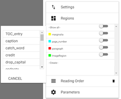 fig. 16. Range of options under ‘Regions’.
- Moreover, the ‘regions’ feature enables the user to assign particular layout regions to a fixed and predefined location on the scan which will then be applied to the following scans. Provided a page’s layout is repeated throughout the entire book, the user can generate something of a layout template in order to improve segmentation and reduce the number of necessary corrections later on. In order to adjust the position of these layout regions to a book’s specific layout, simply display the layout region’s current position and adjust it by selecting the scanned page’s regions.
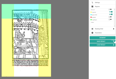 fig. 17. Layout regions display and template.
Once a new region has been defined, its position on the page can be established by clicking on ‘Region’ → ‘Create a region rectangle (Shortcut: 1)’, an option located in the toolbar. This can be undone or changed at any time. Please note that the category ‘images’ can’t be assigned to a layout region on the page.
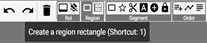 fig. 18. Defining new layout regions.
All things considered, it isn’t always advisable to assign fixed positions to all layout regions for an entire book; if the position of certain regions such as chapter titles, mottos, page number or signature marks on the different pages is inconsistent, assigning predefined positions will lead to recognition errors. In this case, manually verifying and correcting these layout elements afterwards is the more practical approach. If the user needs to delete a layout region’s position, they can simply select the region in question and press the ‘delete’ key.
- 'Parameters': Allows to define overall parameters of image and text recognition. Taking the time to pre-set certain book-specific parameters is recommended when working with an inconsistent layout, particularly that of early modern prints. These often feature great divergences of word and line spacing. To avoid a narrowly spaced group of lines from being recognised as one cohesive textual element, the ‘text dilation’ feature enables you to control and define the text’s degree of dilation in the x- and y-direction. This will enable the software to recognise originally too close word/line spacing or to recognise widely spaced passages as one cohesive element. We recommend trying and testing in order to find the settings best suited to a particular book.
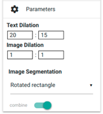 fig. 19. Parameters settings.
- 'Settings': Under ‘Settings’ you can save the previously selected displaying and segmentation options as well as loading them anew after an interruption in segmentation (buttons ‘save settings’ and ‘load settings’). Saving will generate an XML file which you will need to select when loading the settings (click on ‘load settings’, a new window will open; select file in question and open it). An additional feature will enable you to re-load previous pages’ segmentation results if you wish to view them again: simply go to ‘advanced settings’ and click on ‘load now’. This will load any previously saved XML file containing that page’s segmentation results.
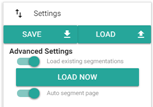 fig. 20: Settings.
- 'Reading Order': In order for the correct order of a page’s textual elements to be taken into account in all steps following segmentation, it is necessary to define these elements’ ‘reading order’ beforehand. This can be done automatically provided a book’s layout be relatively clear and simple. However, should you be working with a more complex layout structure, we recommend you proceed manually. Simply select ‘auto generate a reading order’ or ‘set a reading order’ under toolbar item ‘Order’.
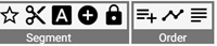 fig. 21. Reading order selection in toolbar
By clicking on the auto reading order button, a list of all the page’s textual elements will appear in the right sidebar (under ‘reading order’), sorted from top to bottom. On the other hand, if you wish to manually establish reading order, you will need to click on each of the page’s textual elements, in the correct order (see below), after which this reading order will appear in the aforementioned list. All elements of the reading order can be rearranged with a drag-and-drop or deleted by clicking on the corresponding recycle bin icon. As with everything in LAREX, the reading order can always be changed before saving the final segmentation results.
Exemplary page segmentation
With each page loading, LAREX automatically generates segmentation results – these only need to be subsequently corrected. The following, exemplary segmentation process uses page 4 of reference book Cirurgia, which you can download here when downloading the OCR4all folder structure.
Error analysis: Which layout elements were correctly recognised, which incorrectly, which weren’t at all? Are there any user marks in the margins, bordures, spots or elements of text which will influence segmentation, but you wish to avoid being recognised?
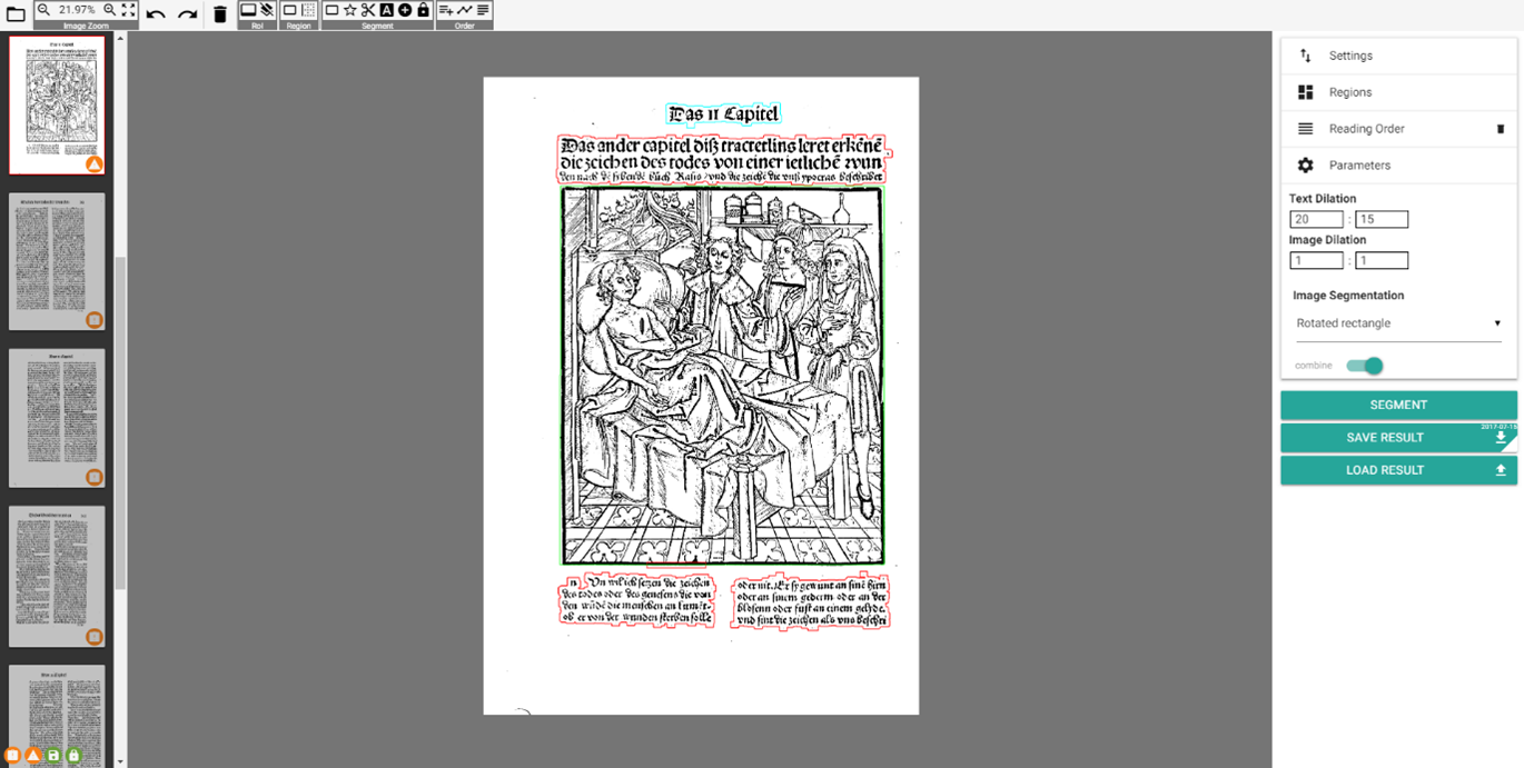 fig. 22. Auto generated results, Cirurgia page 4.
'Region of interest' (RoI): Defining a RoI will help exclude certain sections of your page, situated outside the area later subjected to recognition but which can negatively impact segmentation (such as user marks, impurities, library stamps, etc.). To do so, go to toolbar and click on ‘Set the region of interest’ (under ‘RoI’), then use left click-and-hold to draw a rectangle around the page section you wish to segment.
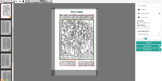 fig. 23. Defining a 'region of interest'.
Once RoI has been defined, click on 'SEGMENT' button (right sidebar) – all element situated outside of RoI are now excluded from any further steps. Once RoI has been defined, it will be automatically transposed to all the book's scans. However, due to a wide array of factors, the page sections relevant to segmentation can shift from scan to scan. Therefore, as processing progresses, the user will likely need to adjust RoI from time to time. To do so, simply click on any RoI section and shift it using the mouse. Independently of RoI, the 'Create an ignore rectangle' option creates an 'ignore region' which allows for certain, small sections of a scan to be ignored and thus excluded from segmentation.
Correcting layout recognition flaws: Incorrectly recognized layout elements can be assigned a new typification manually: a right-hand click on said element will open a pop-up menu from which you can choose the correct designation.
 fig. 24. Correcting a faulty typification.
Should you need to separate a title from another textual element with which it is fused, there three ways to proceed: To begin, you can draw a rectangle around the section you wish to classify: proceed to toolbar, click on ‘Segment’ and select ‘Create a fixed segment rectangle’ (shortcut: 3); using mouse, draw a rectangle around the relevant section – a pop-up menu will appear from
which it’s correct designation/type can be chosen. Next, you can instead choose to use a polygon shape. This option is particularly suited to the more complex or chaotic layouts and/ or those comprising angled edges, rounded pictures and woodcuts, or ornate initials inside the text block. Proceed to toolbar, click on ‘Segment’, this time selecting ‘Create a fixed segment polygon’ option (shortcut: 4). Using the mouse, generate a dotted line to go around end encompass the entire relevant section – once the line’s end has been joined to its starting point, creating a polygon, the aforementioned pop-up menu will appear to allow for designation. Finally, you can also separate a text block – Initially recognized as one paragraph – into a title and main text using a cutting line: simply go to toolbar and ‘Segment’, and select ‘Create a cut line’ option (shortcut: 5).
fig. 25. Toolbar: selecting cut line option.
Using left mouse key, create a line through the element you wish to separate, clicking along its path to adjust it as needed; end line with a double click.
 fig. 26. Drawing a line between two layout elements to be separated.
Click on 'Segment' in order to prompt separation. Afterwards, title element can be correctly renamed, using right-hand click and pop-up menu (as shown below).
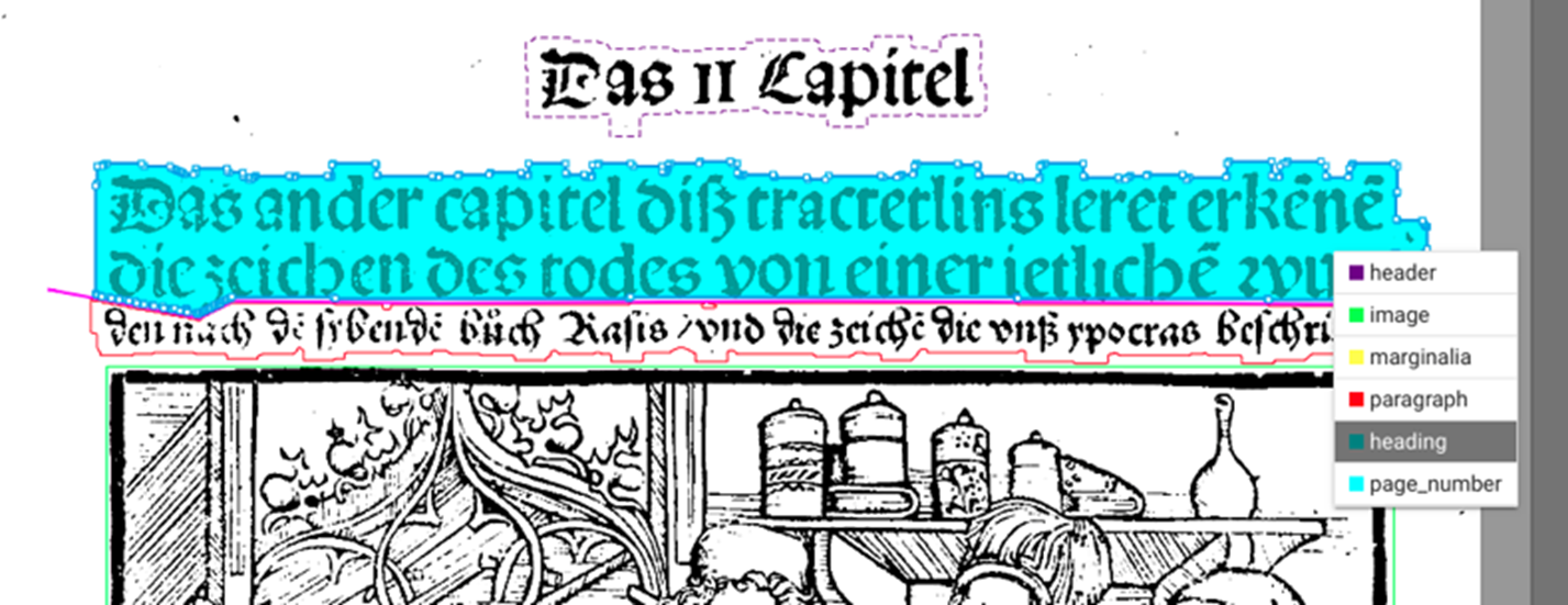 fig. 27. Correcting typification of separated sections.
If at any time you with to delete layout components, inaccurate cutting lines or polygons, etc. simply click on the relevant element and use ‘Delete’ key or ‘Delete selected items’ option in the toolbar.
Determining 'Reading Order' (see below):
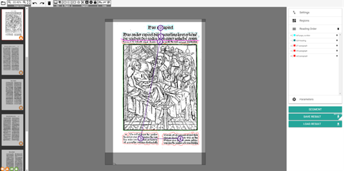 fig. 28. Determining reading order.
Saving current scan’s segmentation results: Save your segmentation results by clicking on ‘Save results’ or with Ctrl + S. This will automatically generate an XML file containing those results inside the OCR4all folder structure.
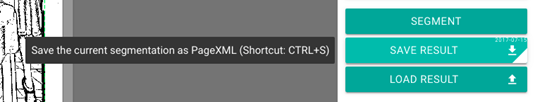 fig. 29. Saving segmentation results.
Afterwards, you can proceed to the next scan (left sidebar). If you wish to redo or change a scan’s segmentation, you can do as much at any time: simply save the new results – the previous XML file will be automatically deleted and replaced with a new version.
Additional processing options
OCR4all also provides the following scan processing options:
- While deleting layout elements or joining separate ones to form one, single region, you can select all relevant elements simultaneously by pressing and holding 'Shift' key and drawing a rectangle around the entire region using your mouse. Relevant regions must be located entirely inside the rectangle. Once done, selected region will be surrounded by a blue frame.
- 'Select contours to combine (with 'C') to segments (see function combine)' (shortcut: 6): this tool is perfect for reaching optimal segmentation results even when working with scans featuring a densely packed and detailed print layout. The basic idea is that layout elements only be delimited by the contours of the individual letters/pictures they are composed of, thus solving the problems created by manual segmentation such as excessively broad margins, which can in turn hamper the OCR performance. To use this feature, click on the relevant button (toolbar) or use shortcut 6. All components of the scan recognized as layout elements will be coloured blue.
 fig. 30. Showing contours.
Select individual letters or even parts of letter by clicking on them.
 fig. 31. Selecting contours.
You can also apply your selection to an individual group of letters, entire words or text lines, sections of a layout element (see above: ‘Shift’ + selection with rectangle). Use shortcut C after selection in order to include all selected items – be they letters, words, lines, etc. – in one, new layout element, regardless of the layout region they had previously belonged to. This new element’s edges will be far more precise that those of an automatically generated one, enabling a particularly accurate segmentation superior to that of standardised tools.
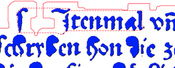 fig. 32. Aggregating selected items to create new element.
Save new element by clicking on ‘Segment’. New element can be renamed as described above.
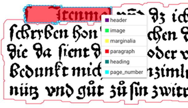 fig. 33. Typifying new layout element.
- 'Combine selected segments or contours' (shortcut: C): In order to combine several, distinct layout elements into a new element, select the entire region in question (see above) and click on corresponding button (toolbar) or use shortcut C.
- 'Fix/unfix segments, for it to persist a new auto segmentation' (Shortcut: F): This function enables you to fix an element in one place beyond your next segmentation rounds. Mark element in question by clicking on it, then use shortcut F or corresponding button in toolbar. Fixed, i. e. pinned elements will appear surrounded by a dotted line. If you wish to cancel fixation, simply repeat the operation.
- Zoom: Use mouse wheel to zoom in and out of display. Use space key to reset display to its original size.
- When working with a very complex and intricate layout, targeted interventions can help increase the precision and quality of segmentation results. The contours of all layout elements (recognized as such) consist in fact of many individual lines, separated by dots.
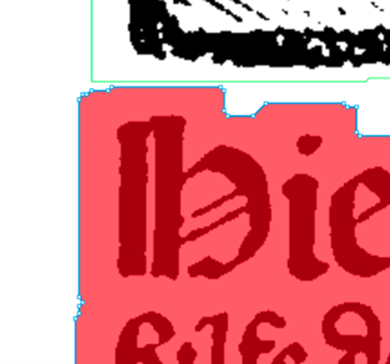 fig. 34. Layout element contours.
- These tiny dots can be moved, individually or in groups, e.g. to avoid collision between different layout elements in a dense setting. Use a left click-and-hold to move a dot, click on the line to create a new dot, use 'delete' key to delete a dot.
- Load results: a scan’s existing segmentation results will be sourced from OCR4all folder structure and directly loaded to LAREX.
Final steps with LAREX
Once a document’s entire segmentation has been completed with LAREX (i.e. once segmentation results have been saved for all pages), results can be found in the OCR4all folder structure. In order to make sure that results were correctly saved, simply go to menu item ‘post correction’, in the ‘segments’ bar (see below).
Line Segmentation
Input: pre-processed images and segmentation information (in the form of PAGE XML files)
Output: extracted text lines saved in those PAGE XML files
- This step constitutes a direct preparation to the OCR process and features the dissection of all previously defined and classified layout elements into separate text lines (this a necessary step as the OCR is based on line recognition). All results are then automatically saved in the corresponding page XML files.
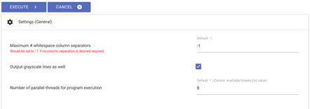 fig. 35. Line segmentation settings.
- Generally speaking, all existing settings can be retained. There are, however, a few restrictions when it comes to page layout: if you are working with pages featuring two or more text columns (and if those have been previously defined as separate, individual main text blocks in LAREX), you will need to change the ‘maximum # of whitespace column separators’ which is pre-set at -1.
- 'Whitespace column separators' are the white columns devoid of text found around text blocks.
- When working with a two-column layout whose text is continuous (i.e. where the first line of both columns don’t form a semantic unit), you will need to set the ‘maximum # of whitespace column separators’ at 3. This number corresponds to the whitespace on both sides of the columns and to the whitespace situated between them.
- When working with a three-column layout, set the 'whitespace' number to 4, and so on.
- Once all desired settings are chosen, click on ‘execute’. Afterwards, control generated results under ‘Project Overview’.
- Using the ‘settings (advanced)’ option is especially useful when working with line segmentation, particularly if/when errors are reported (and shown on the interface). For instance, small letters will often fall short of the default minimal line width. You can adjust this minimal width by reducing the ‘minimum scale permitted’, which can be found under menu item ‘limits’. This will enable you to correctly re-do the line segmentation.
- You can generally control the accuracy of line segmentation by clicking on the ‘lines’ button (under menu item ‘post correction’).
Recognition
Input: Text lines and one or more OCR models
Output: OCR-output in the form of text for each of the PAGE XML files at hand
- This step is where the actual text recognition takes place based on the individual lines and textual layout elements identified during line segmentation (see above).
- Select menu item 'Recognition': in the right sidebar, you will only find your document's scans (or rather printed pages) for which all OCR pre-processing steps have been completed, by which we mean all previously explained steps - bar 'noise removal'. Please select the scans for which you wish to produce an OCR text.
- Go to 'line recognition models' (under 'available') and select all models or model packages relevant to the typographical recognition of your text (e.g. early modern/historical Gothic type, italic/cursive type, historical Antiqua etc.). We expressly advise the use of a model package, where five models simultaneously work and interact with each other! This is much preferable to using only one model at a time. You can select all models you wish to add to your package by clicking on each of them - they will automatically be added to the 'selected' category. When dealing with a large amount of models, you can find them by using the 'search' function.
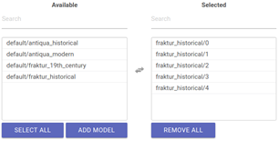 fig. 36. Selection of model package for text recognition.
- You likely won't need to adjust any of the advanced settings.
- Click on 'execute' and oversee the text recognition progress on the console.
- Once recognition is finished, you will be able to view all results under menu item 'ground truth production'.
Ground Truth Production
Input: text line images and their corresponding OCR output when available
Output: line based ground truth
- Under menu item 'ground truth production' you will be able to view the texts generated during 'recognition', correct them and save them as a training model. This is the so called 'ground truth'.
- The correction tool used in this step is divided into two parts. On the left handside are the (selectable) scans. In the middle, you will find the segmented text line images (see above for workflow) as well as their corresponding OCR text lines, placed directly underneath. We call this standard display 'text view'.
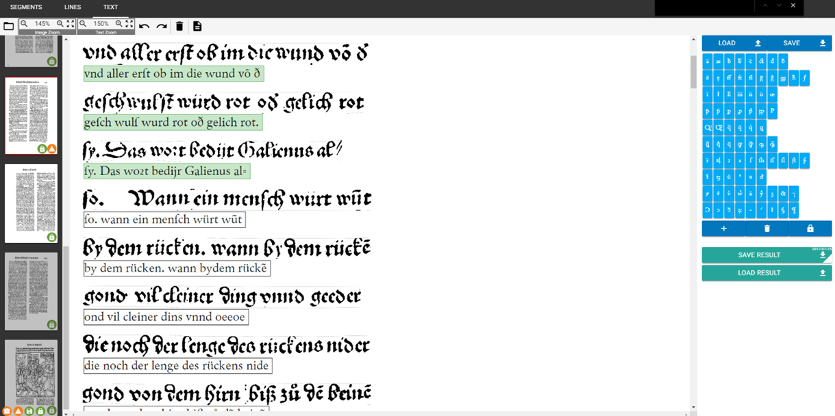 fig. 37. Ground truth production with 'text view'.
Clicking on the 'Switch to page view' button will bring you to the so called 'page view' display, in which you can work on all text lines while they are displayed in relation to the entire page layout. By clicking 'switch to text view', you will return to the initial 'text view' display.
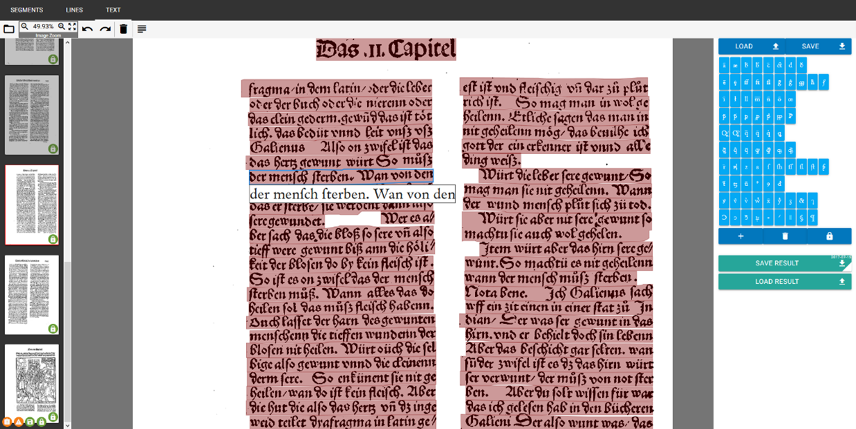 fig. 38. Ground truth production with 'page view'.
- On the right hand side of the display, you will find the virtual keyboard, with which you can set special characters such as ligatures, abbreviation, diacritical signs etc. Simply place your cursor where you with to insert a special character and then click on said character in the virtual keyboard. In order to add new characters to the virtual keyboard, simply click on the plus icon, add character through copy and paste in the blank and click on 'save'. if you wish to delete characters from the virtual keyboard, drag and drop said character on the recycle bin icon. Once all necessary/desired changes have been made, click on 'save' and 'lock'. Using buttons 'lad' and 'save' will ultimately enable you to save different virtual keyboards specific to any particular document. Once a virtual keyboard has been saved as such, it can be re-loaded at any time, which is particularly useful when you need to interrupt correction - or if you want to use this keyboard for another document for which it is suited.
- In order to correct individual lines in 'text view' mode, click on the line in question: you can now correct and edit it. (When working with 'page view', you will need to click on the line you wish to edit first, after which a text field will appear in which you will be able to proceed to corrections/edits as well. Use 'tabulator' key to go to the next line, and so on. All following steps are identical in both viewers. Once a text line has been completely and satisfactorily corrected, press 'enter key'. The line will be coloured green, meaning it will be automatically saved as 'ground truth' in OCR4all once the entire page has been completed and saved (by clicking on 'save result' or using shortcut crtl + S). Once a line has been identified as ground truth, it can be used as a basis for OCR training as well as a tool to evaluate the OCR model you used.
- If there are erroneously recognised text line images among your pairs of text lines images and corresponding OCR text lines, please let your OCR text lines unfilled to not cause problems during the OCR model training.
- Were you to conclude, while working on ground truth production, that the quality of the text recognition achieved with mixed models wasn't satisfactory, you can always perform a final, manual text correction by employing a training model targeted towards the specific kind of document you are working on. Proceeding to this step will generally increase the recognition quality and percentage.
Evaluation
Input: line based OCR texts and corresponding ground truth
Output: error statistics
Under menu item 'evaluation', users can check on the recognition rate of the model(s) currently under use.
In order to generate an evaluation, go to right sidebar and select all the scans recognized with the help of said model and subsequently corrected during 'ground truth production'.
Click on 'execute': a chart will appear in the console. At the top, you will see the percentage of errors as well as the full count of errors ('errs'). All identified errors are listed underneath, displayed as a chart featuring the comparison between the initially recognized text ('PRED', righthand column) and the results of ground truth production ('GT', lefthand column). Behind each error item, you will see the frequency of that particular type of error as well as its percentage compared to the entire error count.
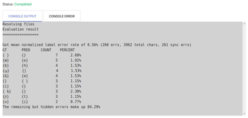 fig. 39. Evaluation results with general error rate, ten most frequent errors as well as their percentage compared to entire error count.
- Thanks to the spreadsheet and its display (100% - error rate), users can evaluate whether a new training using individual, targeted models is necessary.
Training
Input: text line images with corresponding ground truth (as an option, existing OCR models can be included as well, which are used as so called 'pre-training' and as basis for model training
Output: one or more OCR model(s)
The aim of our software is to produce a text containing as few errors as possible. In that case, why is even necessary to use the training module and produce models targeted to your document, instead of simply correcting it manually? In fact, the better a recognition model the shorter the correction time. The idea of a continuous model training is to train increasingly better models through continuous corrections, which in turn will reduce the amount of corrections needed for the next pages, and so on.
- With this training tool, users will be able to train models tailored to their document, based on the lines of ground truth available for this document. In order to begin training, please proceed to the following adjustments in general settings:
- Set the 'Number of folds to train' (i.e. the number of models to train) to 5. → Training will occur with a model package containing five individual models.
- 'Only train a single fold box': please don't fill out this box!
- Set the 'Number of models to train in parallel' at -1. → All training models will be trained simultaneously.
- If all characters contained in the pretraining model need to be kept in the model you wish to train (i.e. added to its so called whitelist), please check the 'Keep codec of the loaded model(s)' box.
- In effect, the 'Whitelist characters to keep in the model' is the exhaustive list of characters used during training and in the subsequently generated model. Any character not contained in the whitelist won't be included in the process.
- 'Pretraining': Either 'Train each model based on different existing models' (a menu will appear containing five dropdown lists. Inside each of them, enter one of the five models belonging to the model package used as advised earlier. Regardless of the training step (be it the first round or the third), always enter the five models used since the beginning) or 'Train all models based on one existing model' (click on this setting if you started training using only one model. Simply select that exact training model for each repetition of the training process).
- 'Data augmentation': Please don't fill out this box! This function describes the data augmentation per line. Users can enter a number, e.g. 5, in order to increase the amount of training material. This can lead to the generation of better performing models. However, this process is more time-costly than the standard route.
- 'Skip retraining on real data only': Please don't fill out this box!
- The advanced settings remain unchanged.
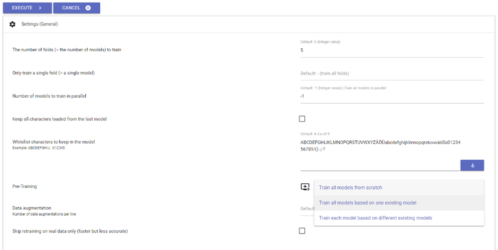 fig. 40. Settings for the training of document-specific models.
- Click on 'execute' to start training. You will be able to view the training progress at any time in the console. Training time will vary depending on the total amount of ground truth lines.
- In accordance with the aforementioned settings, a model package (containing five individual models and tailored to your document's exact needs) will be generated through training and automatically saved in folder ocr4all/models/document title/0. Going forward, this model package will be labelled '0'. From this point on, while working on this document and striving towards improving recognition, you will be able to select said package under menu item 'recognition' among other models, when working with new pages from the same document. If you wish to generate a second document-specific model package (e.g. to improve the first one's weaknesses), simply repeat the process as described above. This new model will be labelled '1', and so on.
Post Correction
Input: segmentation information and metadata on pre-processed scans, as well as the corresponding text
Output: corrected/improved segmentation info and text Under menu item 'post correction', users will be able to manually adjust and correct all segmentation info and text generated through the course of the previous sub-modules. This sub-module is itself divided into three levels:
- The item 'segment' (i.e. level 1) will enable you to adjust all regions determined during segmentation and their reading order, page after page. You will recognize a few of the tools from working with LAREX (see above). Please note that all changes undertaken at this level will have consequences for the following levels. For example, if you decide to delete a certain region during level 1, you will loose all text lines belonging to this region going forward.
- The 'lines' item (i.e. level 2) enables you to manually adjust automatic line recognition. You will be able to add lines where there were none, to change their shape or position, or to delete them. The reading order can be adjusted as well, on a line basis.
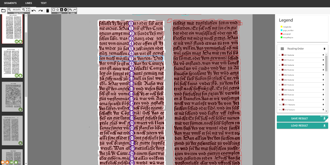 fig. 41. Adjusting line-based reading order during post correction.
- Under item 'text' (i.e. level 3), you will find the afore-described ground truth submodule, in which the text content of your lines can be corrected once more.
Result Generation
Input: line-based OCR results, ground truth (optional - only if at hand) and the LAREX-segmentation and line-segmentation data
Output: final text output (lines will be re-grouped into pages and full-text) as well as page based PAGE XML
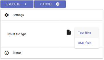 fig. 42: Result Generation.
- Once the user considers all recognition and correction steps to be finalized, results can be generated as TXT or XML files, saved under ocr4all/data/results.
- You can choose whether you need a text or PAGE XML file under 'settings'. If you opt for a text file, individual TXT files will be generated for each scan as well as an additional one containing your document's entire text.
- PAGE XML files are also generated on a page-base and additionally contain data about creation date, last changes in the file, metadata about each page's corresponding scan, about the page's size, its layout regions and their exact coordinates, its reading order, its text lines and their text content.